About the Robot | ||
| ||
Description
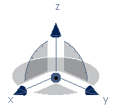
The Robot is displayed by default in the top right corner of the window.
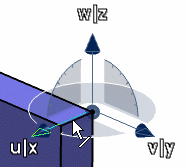
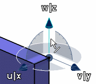
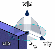
- The Robot has three axes, which are represented by the letters X, Y and Z when the robot is set on geometry. The Z axis is the default orientation.
- The blue sphere is the manipulation handle you use to drag the Robot and place on objects to be manipulated. You can also rotate objects around this point.
- The base of the Robot,
the XY plane, is the privileged plane.
This concept is not useful when simply using Select. It is only useful
for application
commands that use manipulators which require working planes (for
example, when creating planar patches or modifying control points).

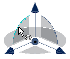
- When the Robot is in the top right corner of the window, the letters
identifying the three axes are not displayed by default. To display
them, right-click the Robot then select Show axis labels:
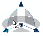
Important: The status of the Show axis labels option (i.e. activated or not) is stored in the settings. Therefore when the option is activated, it remains activated throughout sessions. To hide axis labels again, right-click the Robot then deselect Show axis labels. When the Robot is dropped onto an object, the labels are always visible.
![]()
What Can You Do with the Robot?
The Robot lets you perform various manipulation actions.
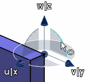
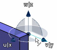
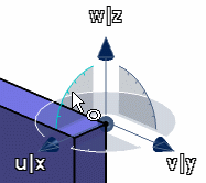
- Manipulate viewpoints using the mouse and Robot: this is just another way of panning and rotating all objects in the document at the same time.
- Move and rotate non-constrained objects using the mouse and Robot. Moving objects in this context means physically moving them so as to redefine their spatial coordinates with respect to the absolute axis system in a document. Moving must not be confused with panning an object, which simply modifies the viewpoint from which you look at an object: the position of the object in the document remains the same.
- Move and rotate non-constrained objects using the Edit... contextual command.
- Lock the Robot orientation.
- Snap the Robot automatically onto a selected object.
- Set the plane in which you move objects parallel to the screen.
- Switch the privileged plane to the XZ or YZ planes of the Robot.
- Use the privileged plane as a working plane in
applications such as the FreeStyle Shaper application, for example, when
manipulating control point manipulators on planar patches and curves.
If you are also using the Assembly Design application, which provides a number of advanced positioning tools, consider the Robot as a preliminary tool for positioning components in space prior to fine positioning of those components within the assembly.
If you are using a space mouse, you can also manipulate the Robot when it is in the scene, otherwise the space mouse lets you manipulate the viewpoint.
![]()
Which Objects Are We Talking About?
You can use the Robot to manipulate non-constrained objects, in other words, objects not linked together by constraints.
However, you can manipulate groups of objects in assemblies which are linked to each other by constraints. You can also snap the Robot to circular objects such as cylinders or axis systems: in that case, the Robot snaps to the cylinder axis or to the axis system's origin.
![]()
Move Objects with the Robot
You can use the Robot to move either a single object, or multiple objects.
When you create a pad, for example, you create it from a sketch which itself is located in a fixed plane, either a reference plane or a plane you create.
When you drag and drop the Robot onto the pad (see Manipulating Objects Using the Mouse and Robot), a message informs you that certain elements in the pad are fixed (the plane from which the sketch was created), and therefore you cannot move the pad.
If you right-click the sketch, then select Parent/Children, you see that the parent of the sketch is a fixed plane. You cannot move the pad until you have either isolated the fixed element (using the Isolate contextual command).
Multiselection is supported by the
Robot but note that if you select an object and its container (part or
product), then the object might be moved twice the distance of the Robot:
- The first move corresponds to the move of the object's container (which implies moving the object as well).
- The second move corresponds to the move of the object itself.
This behavior depends on the positioning constraints between the object and its container: in standard assemblies, the part remains linked to its container, therefore there is no double move whereas in flexible assemblies and in processes, the object moves twice the distance of the Robot.
![]()
Move Objects Using the Edit... Command
You can use translation and rotation increments to translate or rotate the Robot.
The Increment options let you translate or rotate the Robot about the U, V and W axes in increments. When using these options, axes are highlighted according to the increment button you click as shown below:
 |
 |
| Translation along U | Rotation about U |
 |
 |
| Translation along V | Rotation about V |
 |
 |
| Translation along W | Rotation about W |