Adding Steps and Transitions

You can build a SFC graph by adding steps and transitions.

This task shows you how to:


Before you begin:

The SFC+ Editor workbench should be opened. The SFC+ block edited should contain signals and/or ports.

See Sequential Function Chart (SFC+).

Create Steps and Transitions

You can define steps and transitions in the SFC Editor.

  1. Click Add Step then click on the blank page where you want to add the step.

    The step S0 is added in the new sheet. This step is represented by a double line to indicate that it is the initial step.

    The step is also visible in the specification tree.
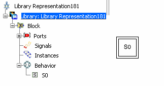


    Note: Double-clicking the icon activates the Add step command to add an unlimited number of steps in the graph.

  2. Add a new step by clicking Add Step again.

    The step and the Counter block turn red, indicating a problem.

  3. Move the cursor over step S1 to display a tool tip.
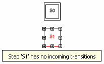


    The message indicates that an incoming transition needs to be added to step S1.

  4. Select step S0 (starting step of the transition), then click Add Transition and select step S1 (ending step of the transition). The red coloring disappears.


  5. Move the step and then select the transition. The transition can be moved by selecting the yellow and red marks.
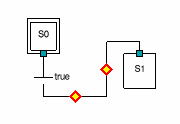


  6. Drag and drop the green mark to disconnect a transition from a step.
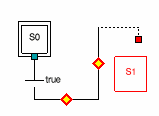


    A transition linked to a step shows a green mark as a link when the transition is selected. The link is red otherwise.

  7. Drag and drop the red mark to a target step to connect the transition and the step.

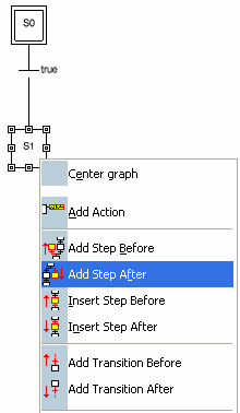
  8. Right-click step S1 and select Add Step After.


Set Step Properties

You can define step properties.

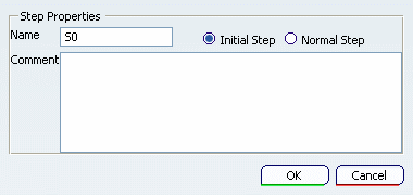
  • Double-click step S0.

    The Step Properties dialog box is displayed.

    The properties of a step are:

    • Name: You can change the name of the step
    • Initial Step/Normal Step: If Initial Step is selected, the step will be the one executed at the first cycle.
    • Comment: The comment is displayed in the tool tip when you move the mouse over the step.

Set Transition Properties

You can set conditions and flags properties for a transition.

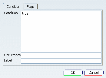
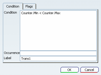
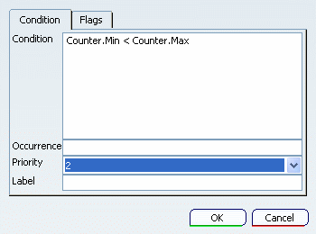
  1. Double-click the transition to set these properties. The Transition Properties dialog box is displayed.


    • Condition: You have to enter a Boolean expression. The transition will be cleared if the condition is true.
    • Occurrence: The number of cycles the condition has to be verified to clear the transition. If not specified, the occurrence is set to 1.
    • Label: If the label is empty, the condition will be displayed in the graph at the right of the transition. If the label is defined, the label is displayed in the graph.

  2. Enter the a Boolean expression in the Condition field. In this example, the structured signal Counter is already defined in the specification tree.


    Note: To enter the signal name in the expression, you can directly click the signal in the tree.

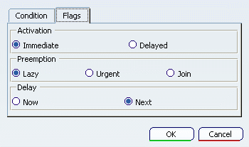
  3. Click the Flags tab.


    You can set the flags of the condition as described below.

    • The Activation flag indicates when the transition is evaluated.


      • Immediate: The transition is evaluated the first cycle the source step is active.

      • Delayed: The transition is evaluated the second cycle the source step is active. This ensures that actions of the source step are executed one cycle before clearing the transition. The graphical representation is a gap in the line.

      Note that the difference in behavior between these two flags stands only for the first cycle that the source step is active.

    • When the transition is true, the Preemption flag is evaluated. This flag defines the execution of the actions of the source step:
      • Lazy: Actions are active for the current cycle, and killed next step.

      • Urgent: The source step is deactivated and its actions killed right away.

      • Join: The transition is cleared when all SFC+ sons of the source step have reached their final step.

    • The Delay flag indicates when the transition is cleared:


      • Now: The target step is activated the same cycle the transition condition is true.

      • Next: The target step is activated one cycle after the condition is true. The graphical representation is a gap in the line.

    Note: A continuous line in the graph determines what is computed within one cycle.

Set Transition Priorities

You can set priorities for alternative SFC branches.

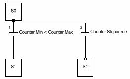
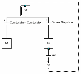
  1. Right-click step S0 and select Add Transition After. A graph with alternative branches is created. At runtime, only one branch can be executed. If the two conditions are true, the branch with the highest priority will be executed.


  2. Right-click a transition to change the priority. A combo box named Priority is available. Change the value to 2. The priority of the other branch is automatically set to 1.


Jump to a Label Layout

You can use labels to map a transition and a step.

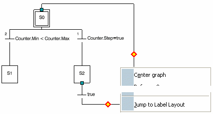
  1. Create a new transition between S2 and S0.

  2. Right-click the new transition and select Jump To Label Layout.


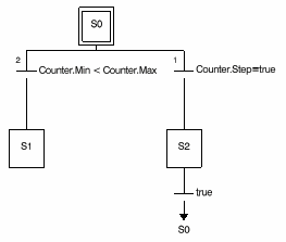
    The link is converted into a label to the step.

  3. Click the transition. A dotted line shows the link to the target step.