Setting Colors of Products and Parts | |||
| |||
Set Color in SFC+
You can insert a Set Color action in a SFC+ graph.
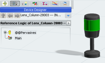
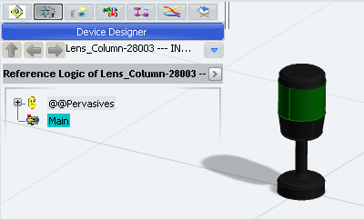
Open a resource that has sub-products in the Live Simulation environment (see a typical example below).
To open the SFC+ Editor, do one of the following:
- Expand the content of the Main block and double-click Behavior.
- Right-click the Main block and select Behavior Editor.
- Select Behavior Editor
 in the Main window toolbar.
A 2D immersive window is opened to edit the block behavior. A toolbox at the right side of the window contains the SFC+ Editor commands.

Note: In our example, the resource logic is undefined, so the editor is empty.
Select Set Color
 in the Activities toolbox.
Select the part to position.
The selected part is highlighted and a bubble attached to it appears.
Tip: Select another part if you want to change the target. Click the bubble to confirm the selection of the product.
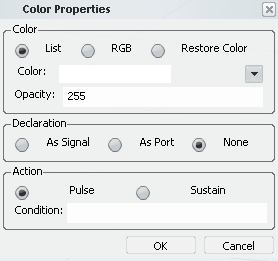
The Color Properties dialog box appears.
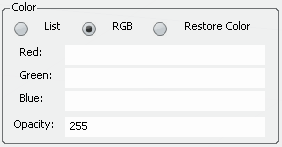
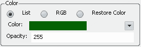
To select the color, you can do one of the following:
- Select Color.
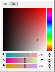
- Click the palette or set the R,G,B values. Then, click outside the palette window to validate your choice.
- Click Basic Colors
 and select a color.
- Select RGB: You have to enter the value of the Red, Green and Blue colors (type: int32, range: 0...255). You can also enter the name of a signal or a port.
Note: If you have entered port or signal names not yet defined in the block, you must check As Port or As Signal in the Declaration frame. The ports or signals are automatically created with the activity.
- Select Restore Color: the color is the color of the product or the part.
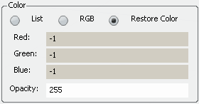
For our example, select Restore Color.
- Select Color.
Click OK. Then, click in the SFC+ Editor to position a new step.
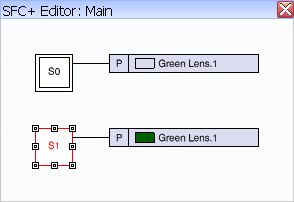
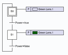
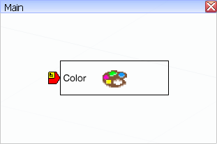
A first step of the SFC+ graph is created. The action contains a square displaying the selected color followed by the name of the product (or the part) being the target of the activity.
Create a new Set color action in the SFC+:
-
Select Set Color
in the Activities toolbox.
- Select the part Green Lens.1 in the 3D view.
- Click the bubble to confirm the selection of the product.
- Select a color.
- Click OK and click in the SFC+ Editor to position a new step.
-
Select Set Color
Select Add Transition
 in the Tools toolbar, click the initial step and then, the second step.
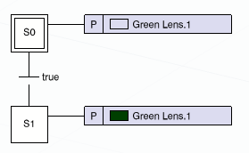
Double-click the transition to change the condition.
Click OK.
The transition appears in red because the signal Power is undefined.Click Add port and change the name of the new port to Power.
Repeat the step 11. and 12. to create a transition between the step S1 and S0. Set the transition condition to Power=false.
To test the behavior of the activity in simulation:
- Select the Main block and click Play
 in the compass.
The block is compiled and the simulation is initialized. The Simulation toolbar and the Signals Monitoring window appear.
- Click Next in the control bar of the compass.
As the first action is to restore the original color, the led does not change.
- Expand the Ports node of the Signals Monitoring window and force the value of Power to true.
- Click Next in the control bar of the compass.
The led is highlighted by the color change.
- Select the Main block and click Play

![]()
Set Color in Dataflow
You can insert a Set Color block in a Dataflow graph. In Dataflow, the color lookup table is not available. You must set directly the R, G, B and opacity values.
Open a resource that has sub-products in the Live Simulation environment. The Main block must be a Dataflow block (see a typical example below).
Double-click the Main block.
A 2D immersive window is opened to edit the block behavior. The Block Editor commands are available in the toolbox at the right side of the window.

Note: In our example, the resource logic is undefined, so the editor is empty.
Select Set Color
in the Activities toolbar.
Select the part to position.
The selected part is highlighted and a bubble attached to it appears.
Tip: Select another part if you want to change the target. Click the 2D editor to position the activity instance.
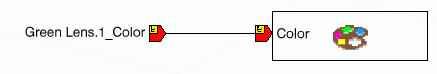
An instance of the color activity is created.
The Color output type is {Red:int32;Green:int32;Blue:int32;Opacity:int32}.
Tip: This type is available as predefined type named Color as soon as the activity Set color is used. Select in the contextual menu of the port Color.
To test the behavior of the activity in simulation:
- Select the Main block thumbnail and click Play in the compass.
The block is compiled and the simulation is initialized. The Simulation toolbar and the Signals Monitoring window appear.
- Expand the Ports node of the Signals Monitoring window and force all the values of Color_IN.
Warning: The color change request is taken into account only if all the ports (Red, Green, Blue and Opacity) are emitted. Do not forget to force the status of a signal if its value does not change. - Click Next in the control bar of the compass.
The led is highlighted by the color change.
- Force the values of Red, Green and Blue to -1. As the Opacity is not changed, just force its status.
- Select the Main block thumbnail and click Play
