Create an Axis System
You can create an axis system by entering coordinates.
Click Axis System
 . . The
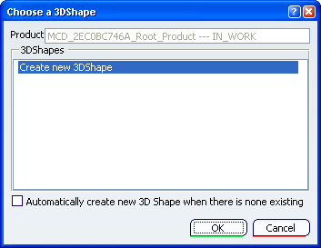
Choose a 3DShape dialog box appears:
The
Choose a 3DShape dialog box displays:
- In the
3DShapes list:
- By default, the list of available and editable 3D shapes in
the active product, otherwise the list of available and editable 3D shapes in a
selected product.
- The
Create new 3DShape option.
- The
Automatically create new 3D Shape when there is none
existing option which allows you to launch directly the
3D Shape / Representation DS dialog box only
when no representation exists under the active product.
Select
the inserted 3D shape in the
3DShapes list and click
OK.
The Axis System Definition dialog box appears.
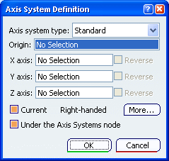
In the Axis system type list, select one of the option:
-
Standard: defined by a point of origin and
three orthogonal directions. If an axis system is selected before launching the command, the new
axis system is a copy of the pre-selected axis system. Moreover, if the
compass is attached to the 3D geometry, the new axis system
orientations are the same as the compass'. Otherwise, the new axis
system orientations are as per the current axis system's.
-
Axis rotation: defined as a standard axis
system and an Angle computed from a selected Reference.
-
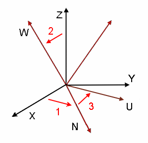
Euler angles: defined by three angle values
as follows:
Angle 1= (X, N)
a rotation about Z
transforming vector X into vector N.
Angle 2= (Z, W)
a rotation about vector N transforming
vector Z into vector W.
Angle 3= (N, U)
a rotation about vector W
In the Origin box, select a point to position the origin of the
axis system you want to create.
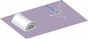
The application then computes the
remaining directions. Both computed axes are then parallel to those of
the current system. The axis system looks like this:
Instead of selecting the geometry to define the origin point, you
can use one of the following contextual commands available from the
Origin box:
Optional: Select the
directions (X axis, Y axis or Z axis).
If you select one
or more directions, the other inputs (directions and origin if not
specified) are automatically computed.
For instance, if you are not satisfied with x axis, click
the X axis box and select a line to define a new direction
for x axis.
The x axis becomes collinear with this line and the application
then computes the remaining directions.
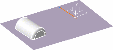
Optional: Click the Y axis in the
3D area to reverse it.
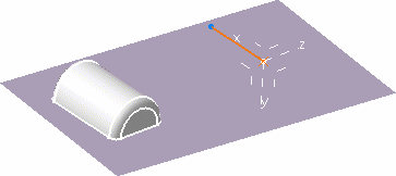
Optional: You can also define axes through coordinates: right-click
one of the axes boxes (X axis, Y axis and
Z axis) and select Coordinates. Enter coordinates in the dialog box that opens and click Close.
The axis system is modified accordingly, in our example it is now
left-handed (see below for more information).
Optional: Click More... to display the More...
dialog box.

The first row contains the coordinates of the origin point. The
coordinates of X axis are displayed in the second row. The
coordinates of Y and Z axis are displayed in the third and fourth row
respectively.
- If no value is selected, the new axis
system matches the current one.
- If the origin is selected, the new axis system origin is set to
the origin.
- The first specified axis defines the corresponding axis of new
axis system. For instance, if the x-axis is specified by Line.1, then the x-axis of new
system is a vector along Line.1.
- The second specified axis defines the plane between the
corresponding first and second axes of the new axis system. For
instance, if the z-axis is specified by Line.2, then the xz plane is
defined by the plane between vectors along Line.1 and Line.2.
- The third specified axis defines the orientation of the
corresponding axis of new axis system. For instance, if the y-axis is specified by Line.3, then Line.3 defines
which side of the xz plane the y-axis of new system lies.
- The order of selection of the axes is important: to change the
order, select the No Selection contextual command on the
appropriate axes.
For instance, if the axes have been selected in the order x, y, z
and you want to change the order to x, z, y, you must select the
No Selection contextual command on y, and select it again.
Optional: Clear the Current check box if you do not want to set your
axis as the reference. The absolute axis at the bottom right of the
document then becomes the current three axis system. Optional: Clear Under
the Axis Systems node if you do not want the axis system to be
created within the Axis system node in the specification tree.
Within the geometrical feature set

Within the Axis System node

It will be created either in the current geometrical
set or right after the current object in an ordered geometrical set.
In this case, the axis system becomes the new current object.


Click OK.
The axis system is created.
When it is set as current, it is highlighted in the specification
tree.
You are now back in Assembly Design workbench.

Edit an Axis System
You can edit the existing axis system.
Double-click the Axis System.1 in the specification tree to edit it. The Axis System Definition dialog box appears. Enter the new values in the dialog box. You can also
use the compass to edit your axis system. Click OK. The axis system is edited. Double-click any product to back in Assembly Design context.
|
![]()