Creating User Patterns | |||
| |||
The Choose a 3DShape dialog box appears:
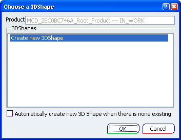
The Choose a 3DShape dialog box displays:
- In the
3DShapes list:
- By default, the list of available and editable 3D shapes in the active product, otherwise the list of available and editable 3D shapes in a selected product.
- The Create new 3DShape option.
- The Automatically create new 3D Shape when there is none existing option which allows you to launch directly the 3D Shape / Representation DS dialog box only when no representation exists under the active product.
- In the
3DShapes list:
Select the element you want to replicate as a pattern.
Note that whenever you are using a feature list, you need to multi-select the features in the order they were created.
The User Pattern Definition dialog box appears.
Warning: The Keep specifications option is unavailable for: - feature lists
- patterning patterns.
Select the sketch needed to position the pattern and click Preview.
Here, it includes the nine points you need to locate the duplicated pockets.
As you just need seven points, click the two points you do not need to unselect them.
Anchor By default, the application positions each instance with respect to the center of gravity or the element to be duplicated. To change this position, use the anchor box: click the Anchor box and select a vertex or a point.Note that contextual commands creating the anchors you need are available from the Anchor box:
- Create Point: for more information, see Creating Points
- Create Midpoint: creates the midpoint of the line you select
- Create Endpoint: creates the endpoint of the line you select
- Create Intersection
- Create Projection
If you create any of these elements, the application then displays the corresponding icon next to the Anchor box. Clicking this icon enables you to edit the element.
Click OK to create the pattern.
The pattern (identified as UserPattern.xxx) is added to the specification tree.
You are now back in Assembly Design workbench.
Warning: - Patterning User Features (UDFs) is not allowed.
- You cannot cut nor copy user patterns.
 .
.