Creating Rectangular Patterns | |||
| |||
The Choose a 3DShape dialog box appears:
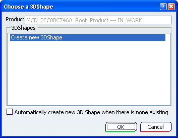
The Choose a 3DShape dialog box displays:
- In the
3DShapes list:
- By default, the list of available and editable 3D shapes in the active product, otherwise the list of available and editable 3D shapes in a selected product.
- The Create new 3DShape option.
- The Automatically create new 3D Shape when there is none existing option which allows you to launch directly the 3D Shape / Representation DS dialog box only when no representation exists under the active product.
- In the
3DShapes list:
Select the element you want to replicate as a pattern.
The Rectangular Pattern Definition dialog box appears.
Each tab is dedicated to a direction you will use to define the location of the duplicated element.
Click the Reference element box and select a direction to specify the first direction of creation.
To define a direction, you may select a line, a planar face or surface edge. You can reverse this direction by clicking the Reverse button.
Click the Second Direction tab to define the same parameters along the other direction of the rectangle.
You can delete instances of your choice when creating or editing a pattern. To do so, just select the points materializing instances in the pattern preview. The instance is deleted, but the point remains, as you may want to click it again to add the instance to the pattern definition again.
Click More>> to display further options.
These options let you position the instances in relation to the first selected element.
Increase the Row in direction 2 to 2.
You notice that the first selected pattern now is the second instance in the vertical direction, as this was the second selected direction.
Simplified representation lets you lighten the pattern geometry, when more than 15 instances are generated. What you need to do is just check the option, and click Preview. The system automatically simplifies the geometry:
Previewed simplified geometry Simplified geometry
You can also specify the instances you do not want to see by double-clicking them. These instances are then represented in dashed lines during the pattern definition and then are no longer visible after validating the pattern creation. The specifications remain unchanged, whatever the number of instances you view. This option is particularly useful for patterns including a large number of instances.
Click OK to create the pattern.
The pattern (identified as RectPattern.xxx) is added to the specification tree.
You are now back in Assembly Design workbench.
Warning: - Patterning User Features (UDFs) is not allowed.
- You cannot cut nor copy rectangular patterns, except if they belong to the same body.
 .
.