Defining an Engineering Connection | ||||||
|
| |||||
Click Engineering Connection
 .
.
The Engineering Connection Definition dialog box appears.
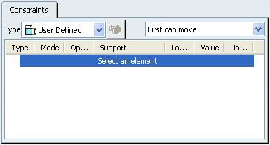
Important: The Engineering Connection Assistant toolbar appears.
These options help you to select/show relevant or irrelevant components to a regular engineering connection, to use constraints in an engineering connection in order to position components.
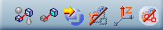
Select Prismatic as engineering connection Type
 .
.
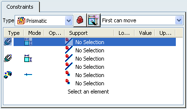
The Engineering Connection Definition dialog box is updated:
- Engineering Connection Type is locked
 .
.
- Engineering connection templates is
enabled
 .
.
Important: According to the selected engineering connection type, Engineering connection templates
is enabled or not.
- Engineering Connection Type is locked
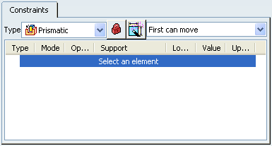
Click Engineering connection templates
.
The Engineering Connection Definition dialog box is updated: a set of constraints and configurations (constraint modes and supports) are suggested.
Click again Engineering connection templates
.
The Engineering Connection Definition dialog box is updated: another set of constraints and configurations (constraint modes and supports) are suggested.
Tip: Click Engineering connection templates
as many times as needed to find the desired configuration.
Click OK in the Engineering Connection Definition dialog.
The Prismatic.1 engineering connection is created.
Important: While the Positioning Mode option is on
 , no engineering connection is created although you click
OK in the
Engineering Connection Definition dialog
box.
, no engineering connection is created although you click
OK in the
Engineering Connection Definition dialog
box.