Constraint Symbols | |||||
|
| ||||
| Constraints | Symbols used in the geometry area | |
|---|---|---|
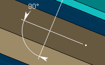
| Angle |
 |
|
| Coincidence |
 / /
|
|
| Curvilinear |

|
|
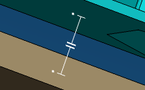
| Contact |
 / /
|
|
| Fix |

|
|
| Fix Symmetry |
/

|
|
| Fix together |

|
|
| Hinge |
|
|
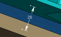
| Offset |
 |
|
| Parallelism |
 |
|
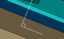
| Perpendicularity |
 |
|
| Roll |

|
|
| Symmetry |
|
|
| Slide |

|
|